Part 1 of 2

Mainshaft Disassembly, Inspection, and Reassembly
1. Inspect the thrust needle bearing and the needle bearing for galling and rough movement.
2. Inspect the splines for excessive wear and damage.
3. Check shaft bearing surface for scoring and excessive wear.
4. Before installing the O-rings, wrap the shaft splines with tape to prevent O-ring damage.
5. Lubricate all parts with ATF during assembly.
6. Install the conical spring washer, 41 x 68 mm thrust washer in the direction shown.
7. Replace the locknut and conical spring washer with new ones when assembling the transmission.
8. Check the clearance of the 5th gear.
Mainshaft 5th Gear Clearance Inspection
1. Remove the mainshaft transmission housing bearing.
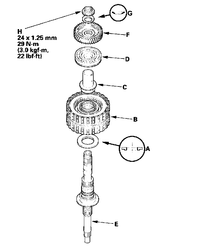
2. Assemble 41 x 68 mm thrust washer (A), 4th/5th clutch (B), 4th gear collar (C), and transmission housing bearing (D) on the mainshaft (E). Do not install the O-rings during inspection.
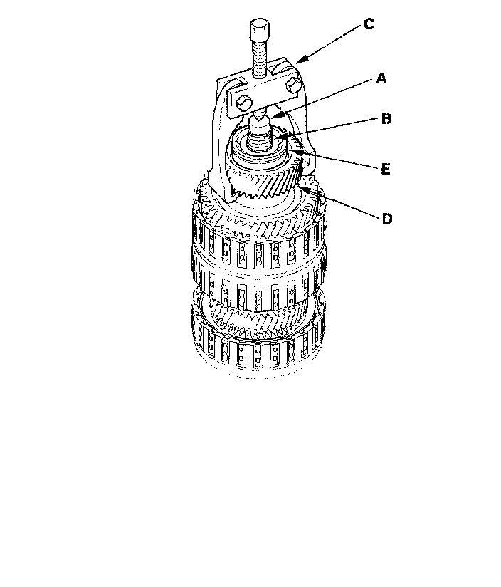
3. Install the idler gear (F) on the mainshaft by a press, then install the conical spring washer (G) and locknut (H).
4. Tighten the locknut to 29 Nm (3.0 kgf-m, 22 ft. lbs.).
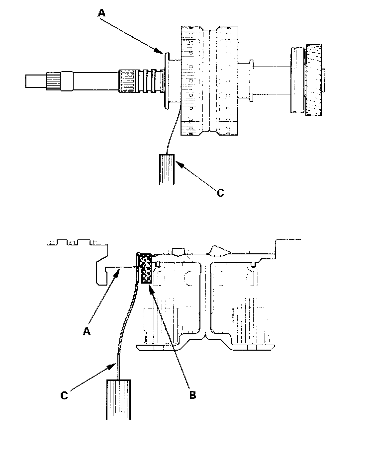
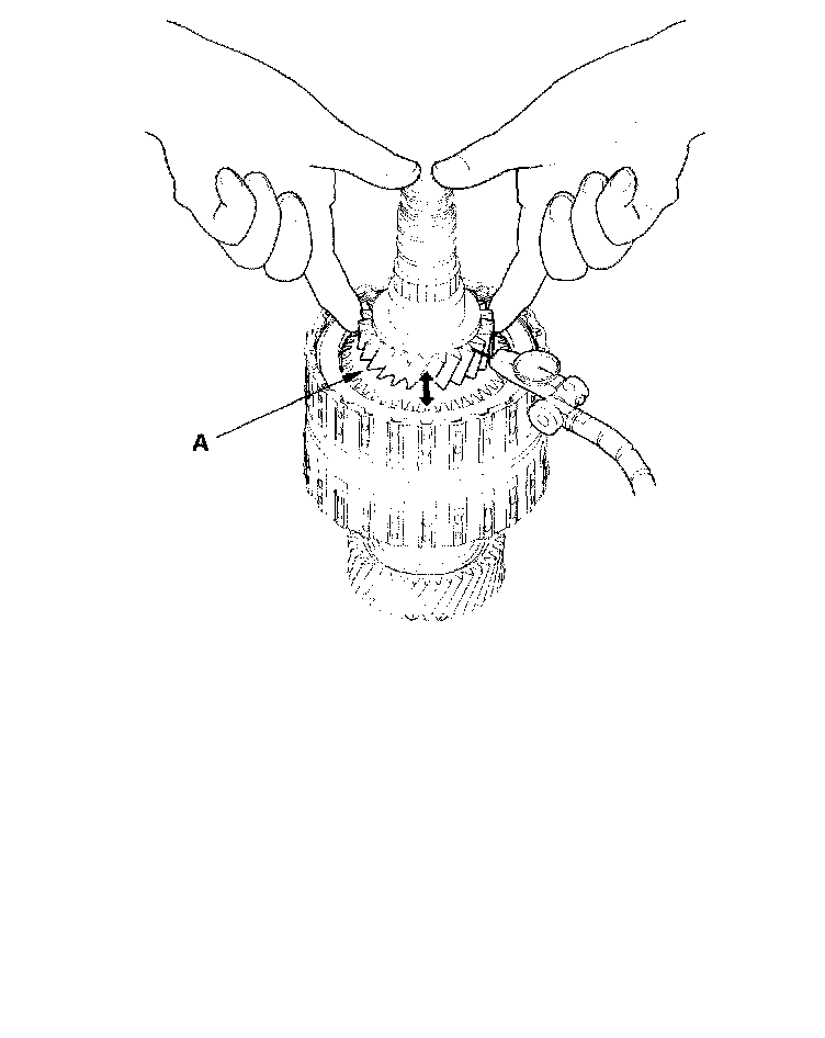
5. Measure the clearance between the mainshaft flange (A) and 41 x 68 mm thrust washer (B) with a feeler gauge (C), in at least three places. Use the average as the actual clearance.
Standard: 0.03 - 0.11 mm (0.001 - 0.004 inch)
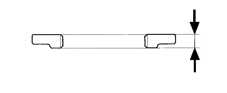
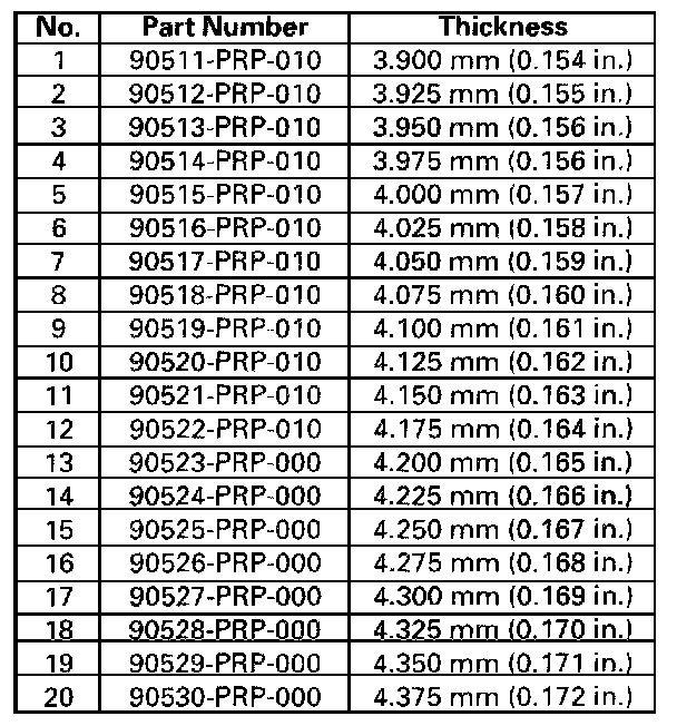
6. If the clearance is out of standard, remove the 41 x 68 mm thrust washer and measure its thickness.
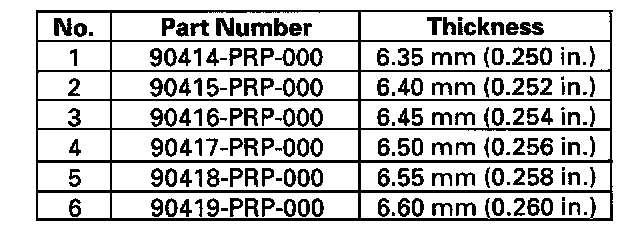
7. Select and install a new thrust washer, then recheck.
8. After replacing the thrust washer, make sure the clearance is within standard.
9. Disassemble the shaft and gears.
10. Reinstall the bearing in the transmission housing.
Countershaft Disassembly, Inspection, and Reassembly

1. Inspect the thrust needle bearing and the needle bearing for galling and rough movement.
2. Inspect the splines for excessive wear and damage.
3. Check shaft bearing surface for scoring and excessive wear.
4. Lubricate all parts with ATF during assembly.
5. Install the conical spring washer, reverse selector, 35 x 47 x 7.8 mm collar, and all gears in the direction shown.
6. Replace the locknut and conical spring washer with new ones when assembling the transmission. The countershaft locknut has left-hand threads.
7. Some reverse selector hubs, and the 3rd gear are press-fitted to the countershaft; special tools are needed to remove them and to install them.
Reverse Selector Hub and 3rd Gear Removal
Special Tools Required
- Bearing separator 07KAF-PS30200
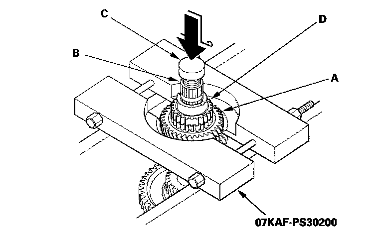
1. Install the special tool on the 4th gear (A). Set a press on the countershaft (B) with putting a spacer (C) between the press and countershaft, and remove the reverse selector hub (D).
NOTE: Some reverse selector hubs are not press-fitted, and can be removed without using the special tool and a press.
2. Remove the needle bearing, set ring, 35 x 47 x 7.8 mm collar, and cotters.
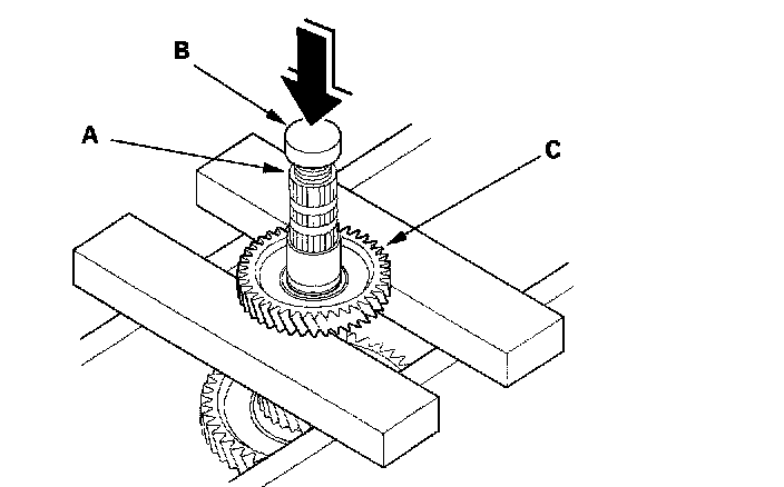
3. Set the press on the countershaft (A) with putting a spacer (B) between the press and countershaft, and remove the 3rd gear (C).
4. Remove the 37 x 41 x 82.8 mm collar, 5th gear, 1st gear, and 2nd gear.
Reverse Selector Hub and 3rd Gear Installation
Special Tools Required
- Driver 40 mm I.D.07746-0030100
1. Install the 2nd gear, 1st gear, 5th gear, and 37 x 41 x 82.8 mm collar on the countershaft.
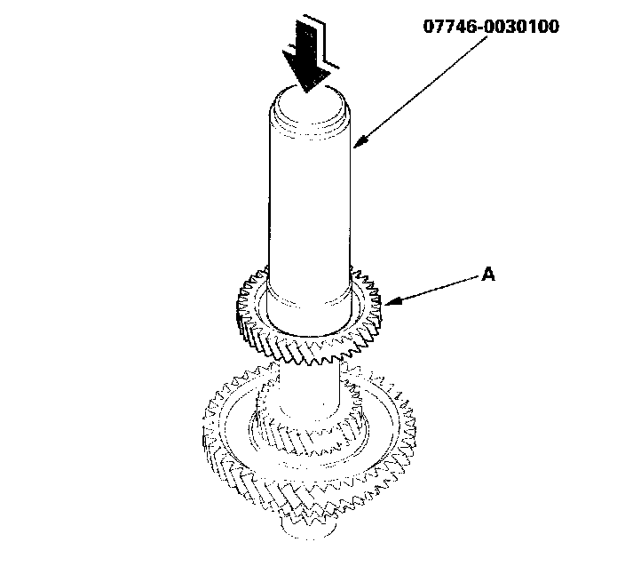
2. Slide the 3rd gear (A) over the countershaft, and press it in place with the special tool and a press.
3. Install the cotters, 35 x 47 x 7.8 mm collar, set ring, needle bearing, and 4th gear.
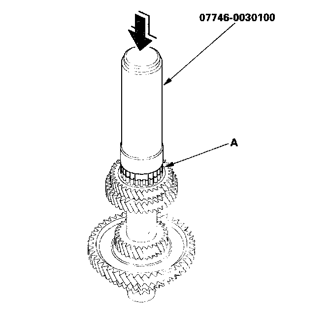
4. Slide the reverse selector hub (A) over the countershaft, then press it in place with the special tool and a press.
NOTE: Some reverse selector hubs are not press-fitted and can be installed without using the special tool and a press.
Secondary Shaft Disassembly, Inspection, and Reassembly

1. Inspect the thrust needle bearing and the needle bearing for galling and rough movement.
2. Inspect the splines for excessive wear and damage.
3. Check shaft bearing surface for scoring and excessive wear.
4. Before installing the O-rings, wrap the shaft splines with tape to prevent O-ring damage.
5. Lubricate all parts with ATF during assembly.
6. Install the conical spring washer, idler gear in the direction shown.
7. Replace the locknut and conical spring washer with new ones when assembling the transmission. The locknut has left-hand threads.
8. Check the clearance of the 2nd gear and 1st gear.
Secondary Shaft Ball Bearing, Idler Gear Removal and Installation
Special Tools Required
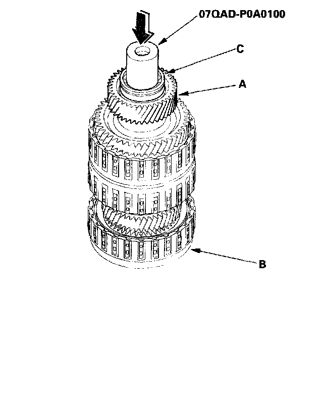
- Attachment, 42 mm I.D. 07QAD-P0A0100
Removal
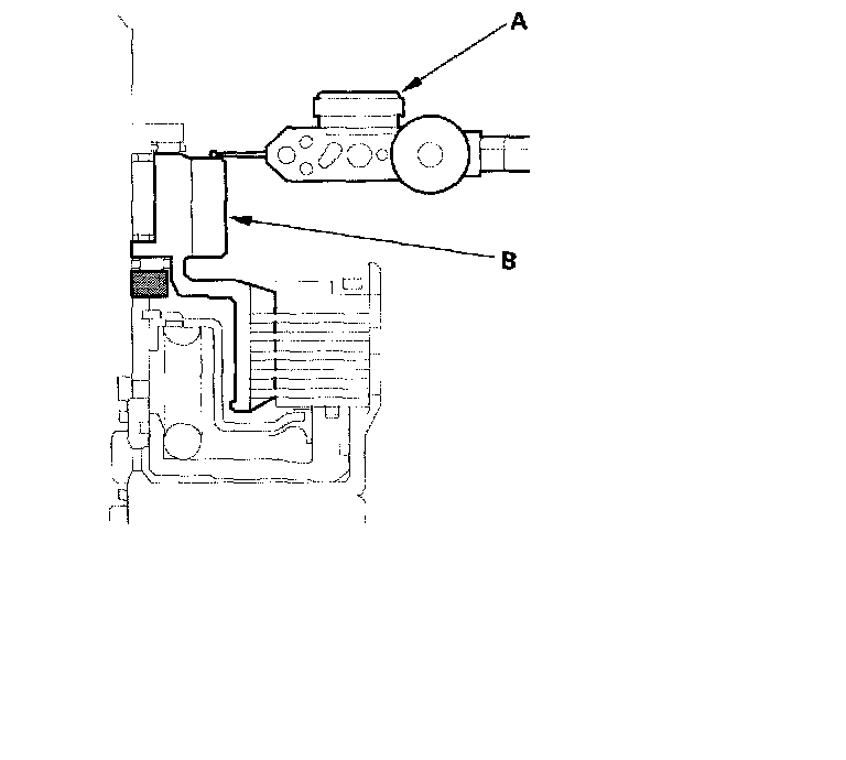
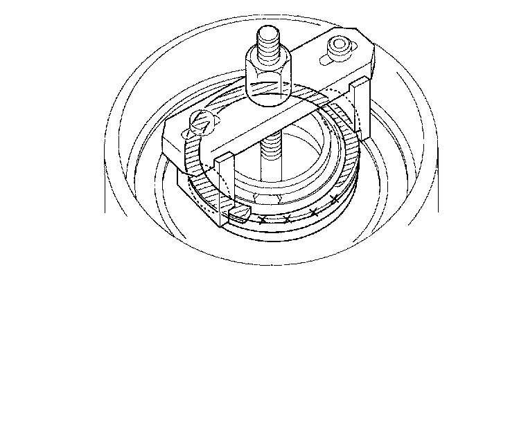
Place a shaft protector (A) on the secondary shaft (B), and set the puller (C) under the idler gear (D), then remove the idler gear and ball bearing (E).
Installation
Install the idler gear (A) on the secondary shaft (B), and install the ball bearing (C) over the idler gear with the special tool and a press.
Secondary Shaft 2nd Gear Clearance Inspection
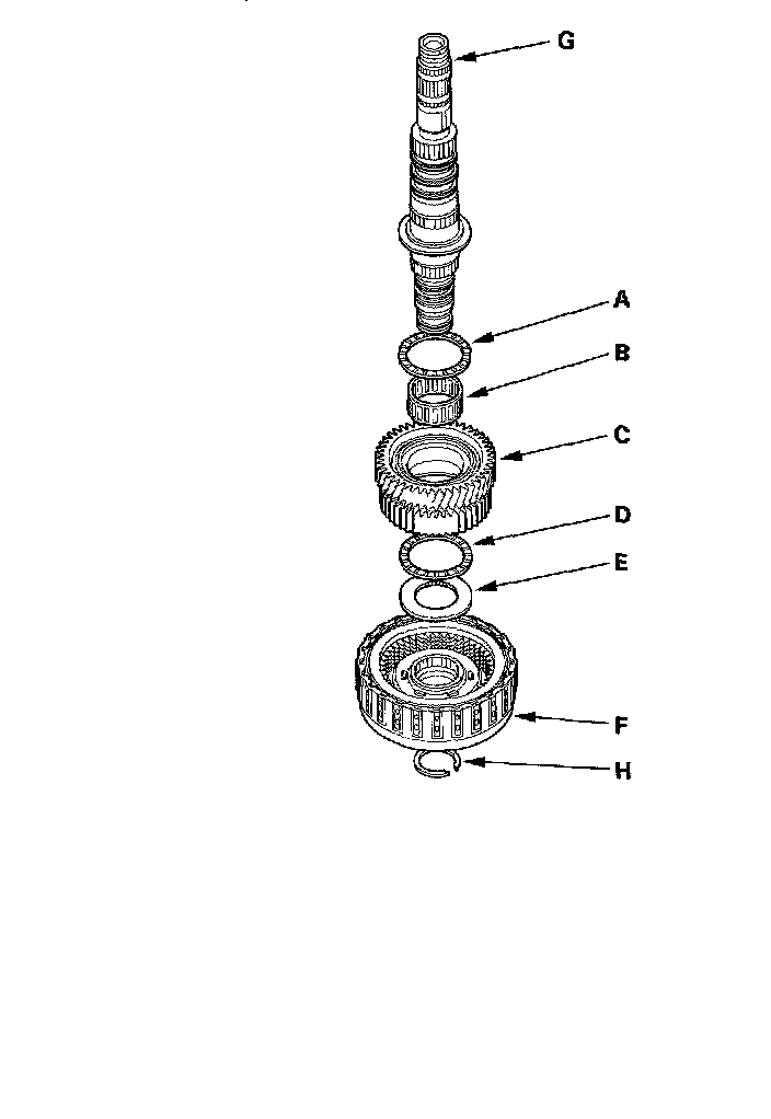
1. Install the thrust needle bearing (A), needle bearing (B), 2nd gear (C), thrust needle bearing (D), 37 x 58 mm thrust washer (E), and 2nd clutch (F) on the secondary shaft (G), then secure them with the snap ring (H).
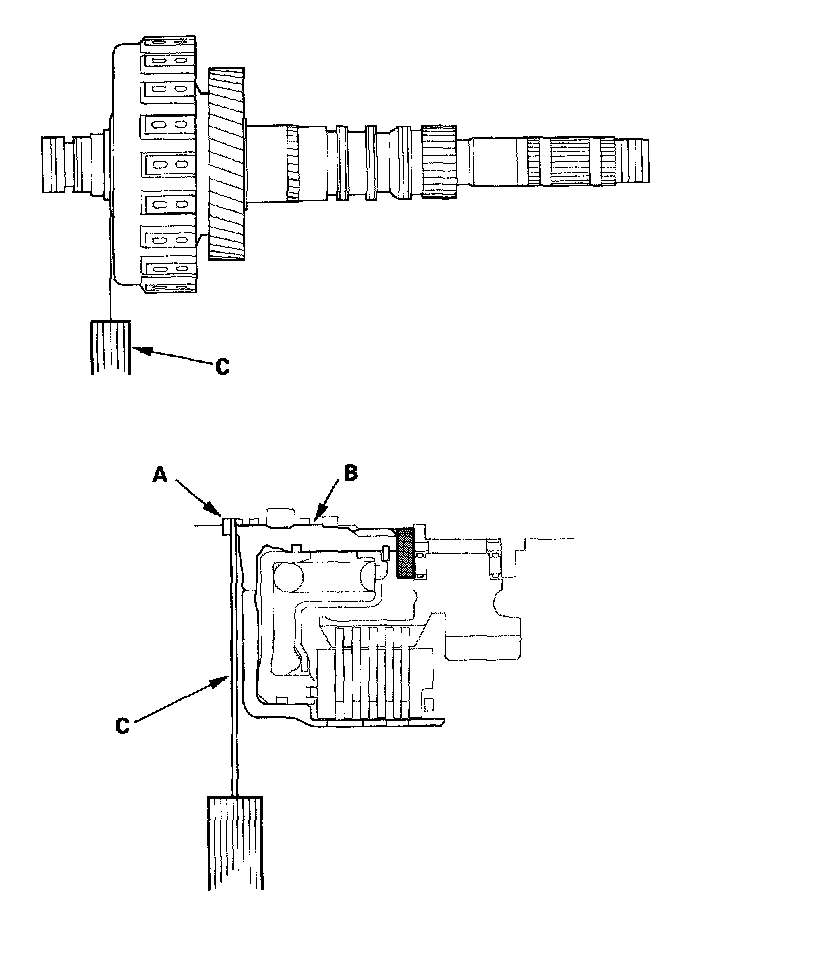
2. Measure the clearance between the snap ring (A) and the 2nd clutch guide (B) with a feeler gauge (C), in at least three places. Use the average as the actual clearance.
Standard: 0.04 - 0.12 mm (0.002 - 0.005 inch)
3. If the clearance is out of standard, remove the 37 x 58 mm thrust washer and measure its thickness.
4. Select and install a new thrust washer, then recheck.
5. After replacing the thrust washer, make sure the clearance is within standard.
6. Disassemble the shaft and gears.
Secondary Shaft 1st Gear Clearance Inspection
Special Tools Required
- Attachment, 42 mm I.D. 07QAD-P0A0100
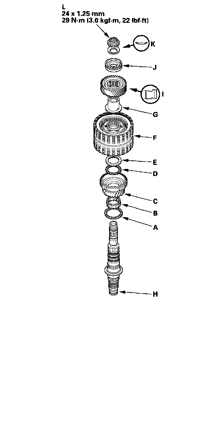
1. Install the thrust needle bearing (A), needle bearing (B), 1st gear (C), thrust needle bearing (D), 40 x 51.5 mm thrust washer (E), 1st/3rd clutch (F), and 3rd gear collar (G) on the secondary shaft (H).
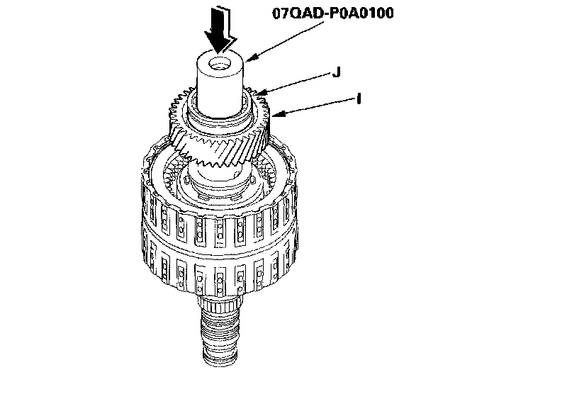
2. Install the idler gear (I), then install the ball bearing (J) on the idler gear with the special tool and a press.
3. Install the conical spring washer (K) and locknut (L), then tighten the locknut to 29 Nm (3.0 kgf-m, 22 ft. lbs.).
4. Turn the secondary shaft assembly upside down, and set the dial indicator (A) on the 1st gear (B).
5. Hold the secondary shaft, and measure the 1st gear axial clearance in at least three places while moving the 1st gear (A). Use the average as the actual clearance.
Standard: 0.04 - 0.12 mm (0.002 - 0.005 inch)
6. If the clearance is out of standard, remove the 40 x 51.5 mm thrust washer and measure its thickness.
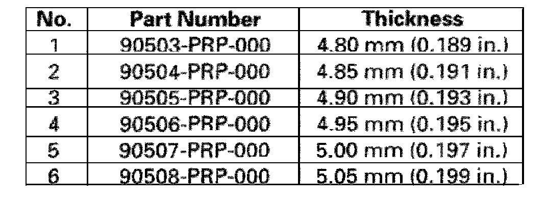
7. Select and install a new thrust washer, then recheck.
8. After replacing the thrust washer, make sure the clearance is within standard.
9. Disassemble the shaft and gears.
Idler Gear Shaft Removal and Installation
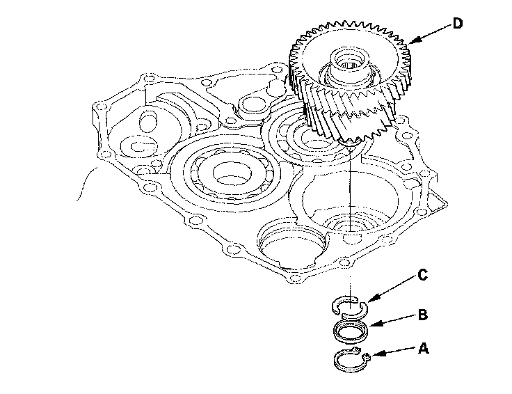
1. Remove the snap ring (A), cotter retainer (B), and cotter keys (C). Do not distort the snap ring.
2. Remove the idler gear shaft/idler gear assembly (D) from the transmission housing.
3. Check the snap rings and cotter retainer for wear and damage. Replace them if they are worn, distorted, or damaged.
4. Install the idler gear and shaft in the reverse order of removal.
Idler Gear/Idler Gear Shaft Replacement
Special Tools Required
- Driver 07749-0010000
- Attachment, 32 x 35 mm 07746-0010100
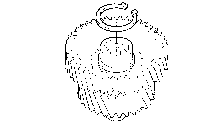
1. Remove the snap ring from the idler gear/idler shaft assembly.
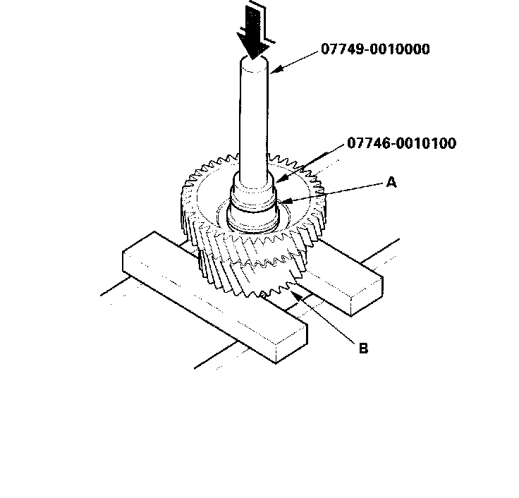
2. Remove the idler gear shaft (A) from the idler gear (B) with the special tools and a press.
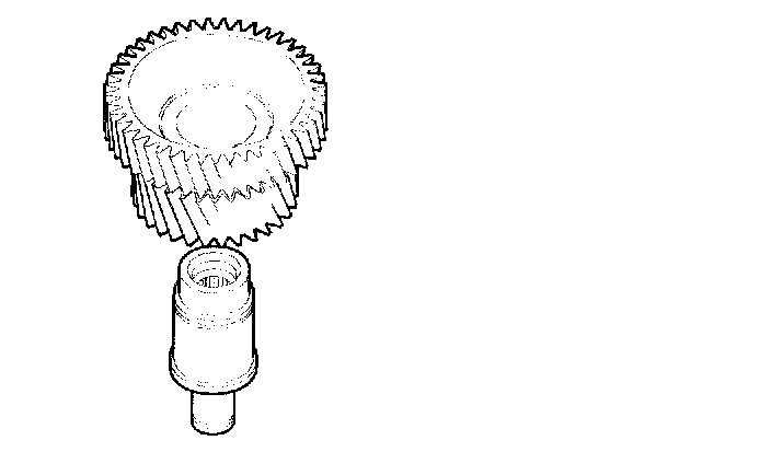
3. Replace the idler gear or idler gear shaft, and attach the idler gear shaft to the idler gear.
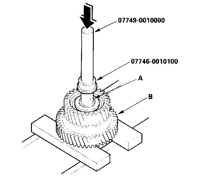
4. Install the idler gear shaft (A) in the idler gear (B) with the special tools and a press.
5. Install the snap ring.
Clutch Disassembly
Special Tools Required
- Clutch spring compressor attachment 07LAE-PX40100
- Clutch spring compressor attachment 07HAE-PL50101
- Clutch spring compressor bolt assembly 07GAE-PG40200 or 07GAE-PG4020A
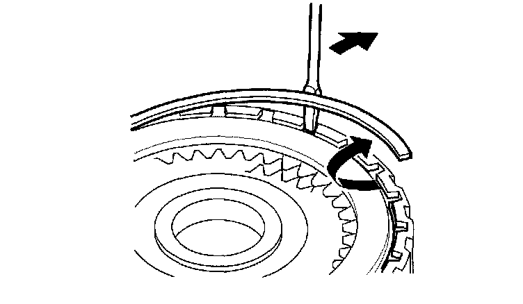
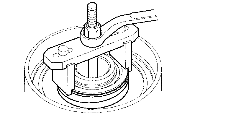
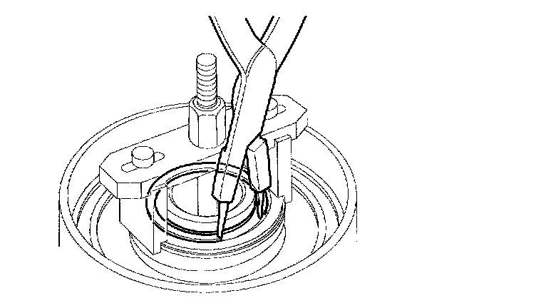
1. Remove the snap ring with a screwdriver.
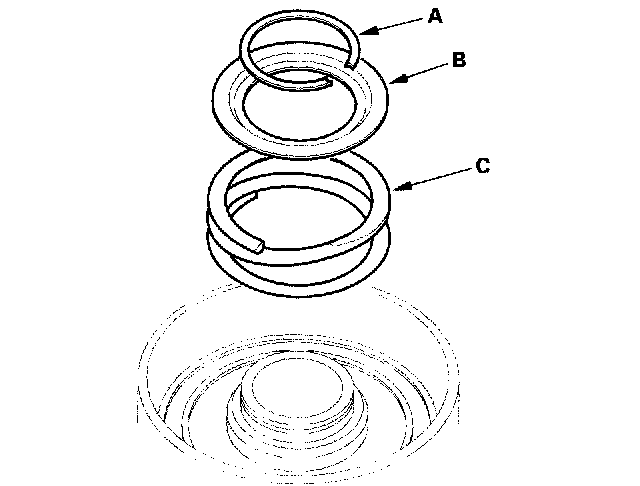
2. Remove the clutch end plate (A), clutch discs (5) (B), clutch flat-plates (5) (C), and waved spring (D) from the 3rd clutch drum (E).
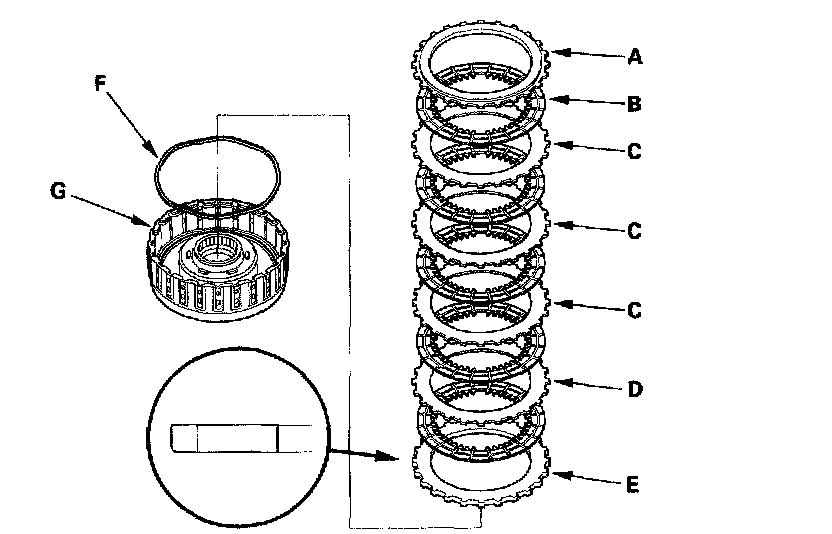
3. Remove the clutch end plate (A), clutch discs (5) (B), clutch waved-plates (3) (C), 2.0 mm-thick flat plate (D), 4.0 mm-thick plate (E), and waved spring (F) from the 2nd clutch drum (G).
4. Make a reference mark on 2.0 mm-thick flat-plate (D).
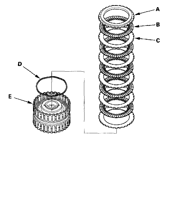
5. Remove the clutch end plate (A), clutch discs (B) (5), clutch flat-plates (C) (5), and waved spring (D) from the 3rd clutch drum (E).
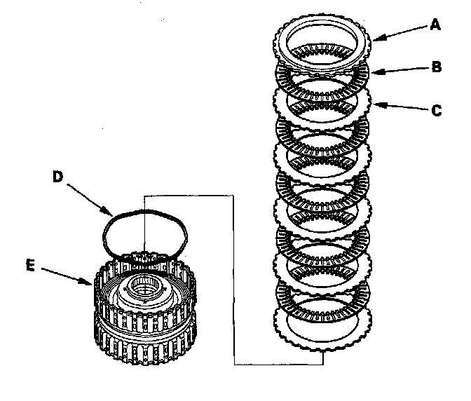
6. Remove the clutch end plate (A), clutch discs (B) (4), clutch waved-plates (C) (4), and waved spring (D) from the 4th clutch drum (E).
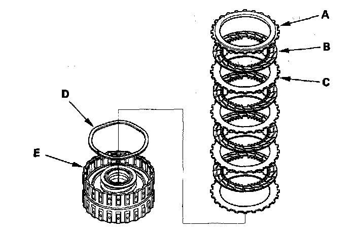
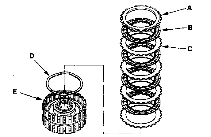
7. Remove the clutch end plate (A), clutch discs (B) (4), clutch waved-plates (C) (4), and waved spring (D) from the 5th clutch drum (E).
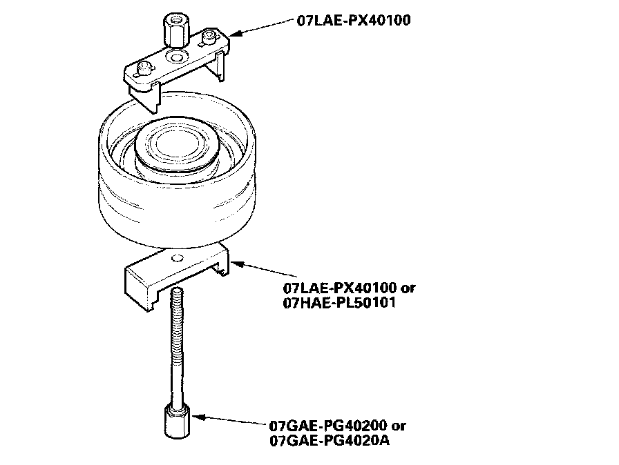
8. Install the special tools.
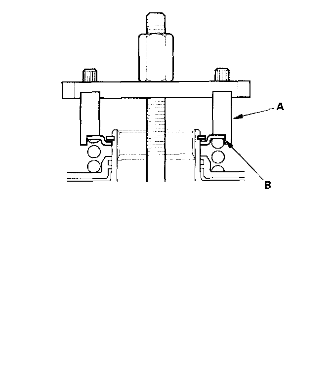
9. Be sure the special tool (A) is adjusted to have full contact with the spring retainer (B) on the 4th and 5th clutches.
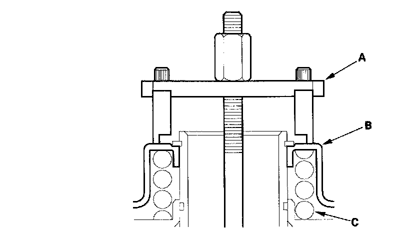
10. Set the special tool (A) on the spring retainer (B) of the 1st, 2nd, and 3rd clutches in such a way that the special tool works on the clutch return spring (C).
11. If either end of the special tool is set over an area of the spring retainer which is unsupported by the return spring, the retainer may be damaged.
12. Compress the return spring until the snap ring can be removed.
13. Remove the snap ring with snap ring pliers.
14. Remove the special tools.
15. Remove the snap ring (A), spring retainer (B), and return spring (C).
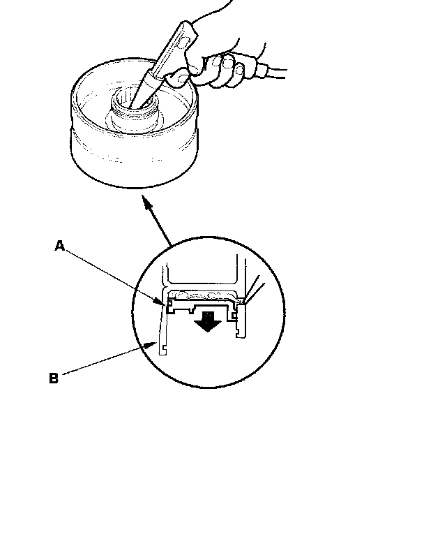
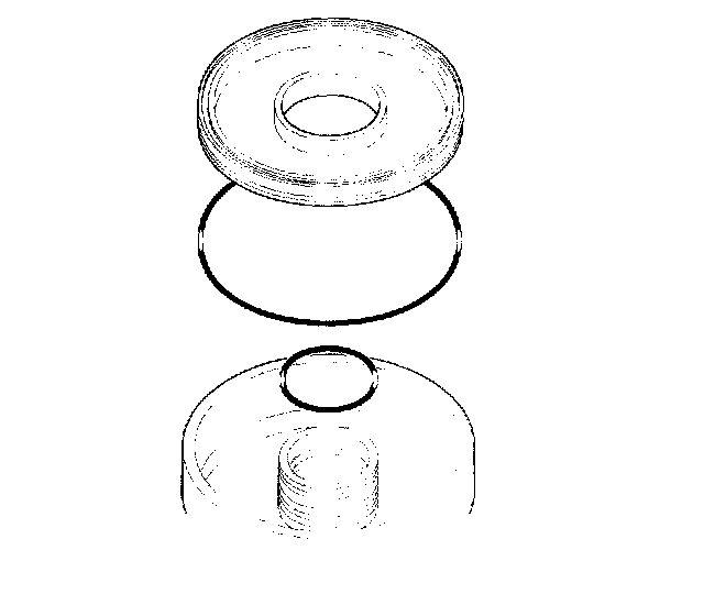
16. Wrap a shop rag around the clutch drum (A), and apply air pressure to the fluid passage to remove the piston (B). Place a finger tip on the other passage while applying air pressure.
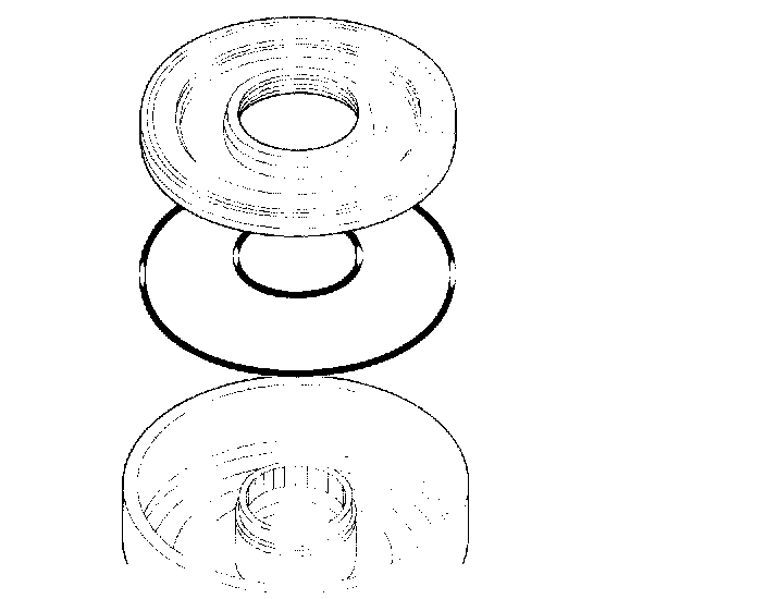
17. Remove the piston, then remove the O-rings from the 4th and 5th clutch pistons.
18. Remove the piston, then remove the O-ring from the 1st, 2nd and 3rd clutch drum, and remove the O-ring from each clutch piston.