A/C and Output Temperature Display Troubleshooting
Audio-HVAC Display Module Illumination Troubleshooting1. Turn the ignition switch to the ON (II) position.
2. Turn the combination light switch ON.
3. Turn the illumination control dial on the gauge control module back and forth between full dim and full bright.
Does the problem with the illumination affect only the audio-HVAC display panel?
YES - Go to step 4.
NO - Go to B-CAN Diagnosis Test Mode A.
4. Turn the illumination control dial on the gauge control module back and forth between full dim and full bright while watching the audio-HVAC display panel buttons, button LEDs, LCD displays and lower panel ambient light.
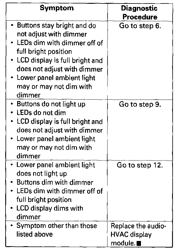
5. Proceed with the diagnostic procedure for the appropriate symptom(s).
6. Remove the audio-HVAC display module and check for loose wires terminals or poor connections at audio unit connector A (20P).
Are all the wire terminals tight, and is audio unit connector A (20P) connected properly?
YES - Go to step 7.
NO - Repair the loose wire terminal, or properly connect audio unit connector A (20P) and recheck the symptom.
7. Turn the illumination control dial on the gauge control module to the full bright position.
8. Measure the voltage between the No.19 and No.20 terminals of audio unit connector A (20P).
Is there 1 V or less?
YES - Check connections at audio unit connector A (20P). If connections are OK substitute a known-good audio-HVAC display module and recheck the symptom. If the symptom is gone, replace the original audio-HVAC display module.
NO - Repair open in the RED wire between the MICU and the audio-HVAC display module.
9. Remove the audio-HVAC display module and check for loose wire terminals or poor connections at audio unit connector A (20P).
Are all the wire terminals tight, and is audio unit connector A (20P) connected properly?
YES - Go to step 10.
NO - Repair the loose wire terminal, or properly connect audio unit connector A (20P) and recheck the symptom.
10. With the combination light switch still ON, turn the illumination control dial on the gauge control module to the full bright position.
11. Measure the voltage between the No.9 and No.20 terminals of the audio unit connector A (20P).
Is there battery voltage?
YES - Check connections at the audio unit connector A (20P). If connections are OK substitute a known good audio HVAC display module and recheck the symptom. If the symptom is gone, replace the original audio-HVAC display module.
NO - Repair open in the RED/BLK wire between the under-hood fuse/relay box and the audio-HVAC display panel.
12. Remove the audio HVAC display module and check for loose wire terminals or poor connections at climate control unit connector B (16P).
Are all the wire terminals tight, and is climate control unit connector B (16P) connector connected properly?
YES - Go to step 13.
NO - Repair the loose wire terminal, or properly connect climate control unit connector B (16P) and recheck the symptom.
13. Turn the illumination control dial on the gauge control module to the full bright position.
14. Measure the voltage between the No.12 and No.6 terminals of climate control unit connector B (16P).
Is there 1 V or less?
YES - Go to step 15.
NO - Repair open in the RED wire between the MICU and the climate control unit.
15. Measure the voltage between the No.8 and No.6 terminals of the climate control unit connector B (16P).
Is there battery voltage?
YES - Check connections at climate control unit connector B (16P). If connections are OK substitute a known-good audio-HVAC display module and recheck the symptom. If the symptom is gone, replace the original audio-HVAC display module.
NO - Repair open in the RED/BLK wire between the under-hood fuse/relay box and the climate control unit.