B-CAN System Diagnosis Test Mode 1
B-CAN System Diagnosis Test Mode 1 (Troubleshooting without the HDS)1. Check the No.7 (10 A) fuse and No.21 (7.5 A) fuse in the under-dash fuse/relay box.
Are the fuses OK ?
YES - Go to step 2.
NO - Find and repair the cause of the blown fuse.
2. Remove the left kick panel.
3. Turn the ignition switch ON (II).
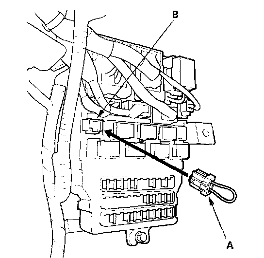
4. Connect the MFCS Service connector (A) to the MCIC socket (B) in the under-dash fuse/relay box.
5. Wait 5 seconds, then watch the ceiling light.
6. If there is a DTC, the ceiling light and ignition switch light will blink, pause, then repeat the DTC as long as the ignition switch ON (II).
Is there a repeating DTC?
YES - Count the blinks, then go to step 7.
NO - Go to step 8.
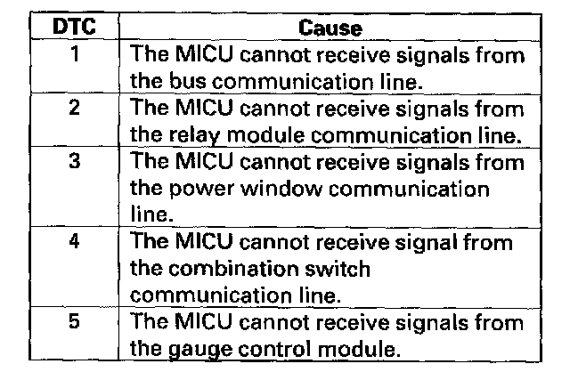
7. About 1 second after you go into self-diagnosis Mode 1, the ceiling light will indicate the DTC, and repeat it every 3 seconds. If there is more than one DTC, the system will indicate them in ascending order, beginning from the DTC with the lowest numerical value. Troubleshoot the DTCs as indicated below:
- DTC 2, 3, 4 and 5 simultaneously: Check for an open in the BLU wire between multiplex integrated control unit D11 and relay module J7, BRN/RED wire between multiplex integrated control unit J4 and door multiplex control unit No.16, LT GRN wire between multiplex integrated control unit X27 and combination switch control unit No.4, BRN/YEL wire between multiplex integrated control unit N28 and gauge B25. If the wire is OK, substitute a known-good under-dash fuse/relay box (multiplex integrated control unit), under-hood fuse/relay box, power window master switch, wiper/washer switch and gauge one at a time, in that order, and recheck for the DTCs after each substitution.
- DTC 1 only: Go to MICU input test.
- DTC 2 only (no other DTCs present): Go to the relay module input test. If all inputs are OK, substitute a known-good relay module and then a MICU, one at a time, and then check for DTCs. If a DTC recurs after a substitution, replace that unit.
- DTC 3 only (no other DTCs present): Go to the door multiplex control unit input test. If all inputs are OK, substitute a known-good door multiplex control unit and then a MICU, one at a time, and then check for DTCs. If a DTC recurs after a substitution, replace that unit.
- DTC 4 only (no other DTCs present): Go to the combination switch control unit input test. If all inputs are OK, substitute a known-good wiper/washer switch and then a MICU, one at a time, and then check for DTCs. If a DTC recurs after a substitution, replace that unit.
- DTC 5 only (no other DTCs present): Go to the gauge control module input test. If all inputs are OK, substitute a known-good gauge control module and then a MICU, one at a time, and then check for DTCs. If a DTC recurs after a substitution, replace that unit.
8. Check for B-CAN DTCs indicated by the gauge control module while still in Test Mode 1.
Are any DTCs indicated?
YES - Go to step 9.
NO - Go to step 11.
9. Record all DTCs and sort them by type using the DTC Troubleshooting Index. DTC List - Body Control System
10. Troubleshoot the DTCs in the following order:
- Battery voltage DTCs
- Internal error DTCs
- Loss of communication DTCs (begin with the lowest number first; for example, if B1006 and B1059 are retrieved, troubleshoot B1006 first)
- Signal error DTCs
11. Remove the MFCS service connector from the under-dash fuse/relay box socket for 5 - 10 seconds, then re-insert it.
NOTE: If the MFCS connector is disconnected for too short or too long of a time, or the ignition switch is turned OFF, the system will return to Test Mode 2.
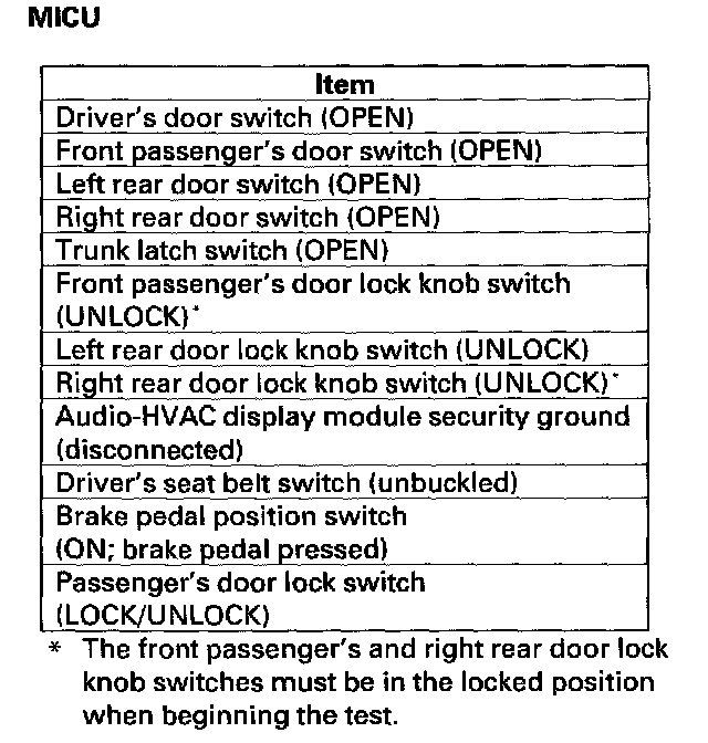
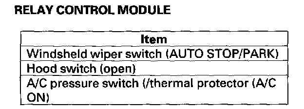
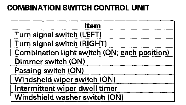
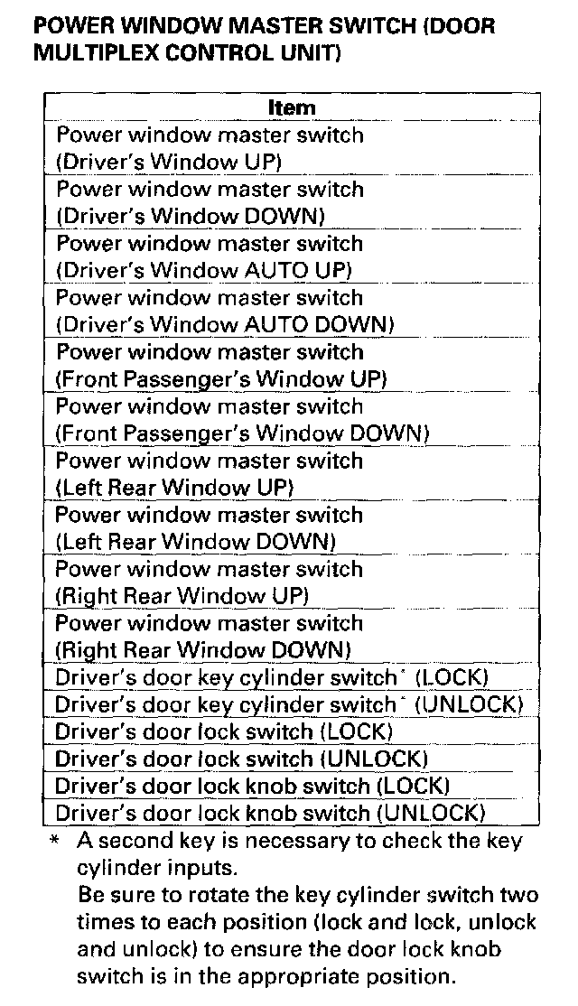
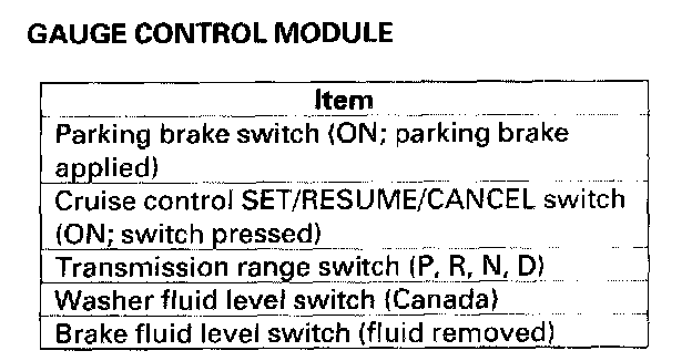
12. In the table given is a list of circuits that can be checked in Test Mode 2. Operate the switch that is most closely related to the problem. If the circuit is OK, the ceiling light will blink once. If the circuit is faulty, there will be no indication.
Does the ceiling light indicate proper switch operation?
YES - Go to function and input test for the system related to the failure.
NO - Repair the open, short, or replace the faulty switch.