U0073
DTC U0073: FCAN Malfunction (Bus-Off)1. Turn the ignition switch ON (II).
2. Clear the DTC with the HDS.
3. Check for Temporary DTCs or DTCs in the DTCs MENU with the HDS.
Is DTC U0073 and/or U0155 indicated?
YES - Go to step 4.
NO - Intermittent failure, system is OK at this time. Check for poor connections or loose terminals at the gauge control module, VSA control unit, the navigation unit and the ECM/PCM.
4. Check for DTCs in the DTCs MENU in the Body Electrical system with the HDS.
Is DTC B1168 B1169 and/or B1178 indicated?
YES - Go to step 5
NO - Perform the gauge control module input test.
5. Turn the ignition switch OFF.
6. Remove the gauge control module.
7. Disconnect the gauge control module 30P connector.
8. Disconnect the VSA control unit 47P connector.
9. If equipped with the navigation system, disconnect the navigation unit 20P connector.
10. Jump the SCS line with the HDS.
11. Disconnect ECM/PCM connector E (31P).
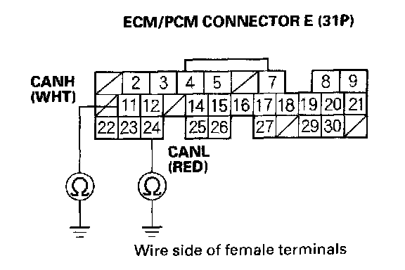
12. Check for continuity between ECM/PCM connector terminals E11,E24 and body ground individually.
Is there continuity?
YES - Repair short in the wire between the gauge control module, VSA control unit, the navigation unit, and the ECM/PCM (E11 (E24)), then go to step 17.
NO - Go to step 13.
*: CANL line
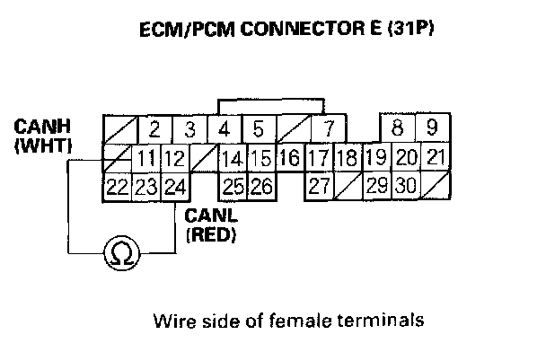
13. Check for continuity between ECM/PCM connector terminals E11 and E24.
Is there continuity?
YES - Repair short in the wire between the ECM/PCM E11 (CANH line) and E24 (CANL line) then go to step 17.
NO - Go to step 14.
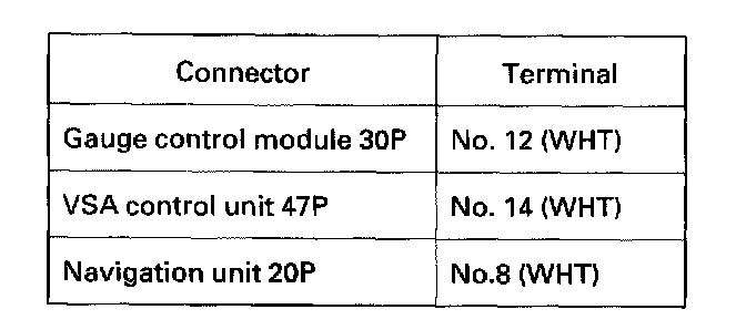
14. Check for continuity between ECM/PCM connector terminal E11 and the given connector terminals:
Is there continuity between the ECM/PCM terminal and each of the terminals in the chart?
YES - Go to step 15.
NO - Repair open in the wire between the ECM/PCM and the appropriate connector, then go to step 17.
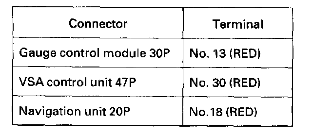
15. Check for continuity between ECM/PCM connector terminal E24 and the given connector terminals:
Is there continuity between the ECM/PCM terminal and each of the terminals in the chart?
YES - Go to step 16.
NO - Repair open in the wire between the ECM/PCM and the appropriate connector, then go to step 17.
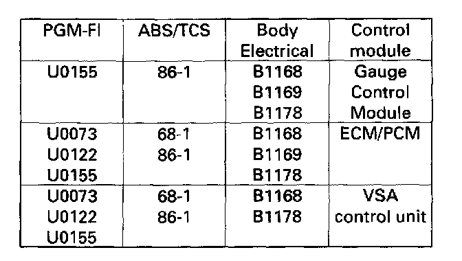
16. Refer to the shown chart. Select the row that most closely represents the combination of DTCs retrieved from the PGM-FI, VSA, and Body Electrical systems: Check connections at the control module indicated in the last column. If all connections are OK, substitute a known-good control module, then go to step 17 and recheck.
Are the DTCs still indicated?
YES - Substitute the remaining control modules, one at time, until the DTCs are no longer present, then replace that control module. After replacing the faulty control module, go to step 17.
NO - Replace the faulty control module, then go to step 17.
17. Reconnect all the connectors.
18. Turn the ignition switch ON (II).
19. Reset the ECM/PCM with the HDS.
20. Do the ECM/PCM idle learn procedure.
21. Check for Temporary DTCs or DTCs in the DTCs MENU with the HDS.
Are any Temporary DTCs or DTCs indicated?
YES - If DTC U0073 and/or U0155 is indicated, check for poor connections or loose terminals at the gauge assembly, VSA control unit, navigation unit, and the ECM/PCM, then go to step 1. If any other DTCs are indicated, go to the indicated DTC troubleshooting.
NO - Troubleshooting is complete.