B1241
DTC B1241: A Problem in the Blower Motor Circuit1. Clear the DTC.
2. Turn the ignition switch OFF, and then ON.
3. Operate the climate control system is several modes.
4. Check the DTCs.
Is DTC N or B1241 indicated?
YES - Go to step 5.
NO - Intermittent failure, check for loose wires or poor connections on the blower motor circuit.
5. Check the No.21 (40A) fuse in the under-hood fuse/relay box, and the No.30 (7.5 A) fuse in the under-dash fuse/relay box.
Are the fuses OK ?
YES - Go to step 6.
NO - Replace the fuse(s), and recheck.
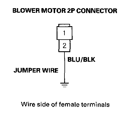
6. Connect the No.2 terminal of the blower motor 2P connector to body ground with a jumper wire.
7. Turn the ignition switch ON (II).
Does the blower motor run?
YES - Go to step 8.
NO - Go to step 22.
8. Turn the ignition switch OFF.
9. Disconnect the jumper wire.
10. Disconnect the power transistor 4P connector.

11. Check for continuity between the No.2 terminal of the power transistor 4P connector and body ground.
Is there continuity?
YES - Go to step 12.
NO - Check for an open in the BLK wire between the power transistor and body ground. If the wire is OK, check for poor ground at G503.
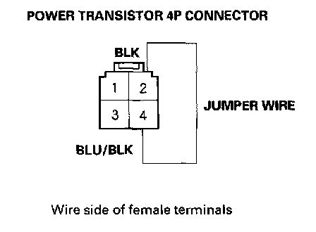
12. Connect the No.2 and No.4 terminals of the power transistor 4P connector with a jumper wire.
13. Turn the ignition switch ON (II).
Does the blower motor run at high speed?
YES - Go to step 14.
NO - Repair open in the BLU/BLK wire between the power transistor and the blower motor.
14. Turn the ignition switch OFF.
15. Disconnect the jumper wire.
16. Disconnect climate control unit connector B (16P).
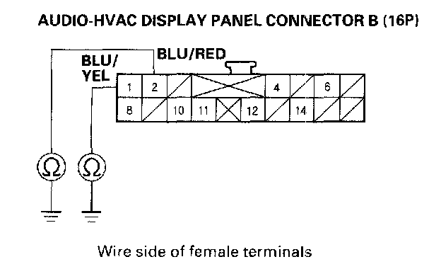
17. Check for continuity between the No.1 and No.2 terminals of audio-HVAC display panel connector B (16P) and body ground individually.
Is there continuity?
YES - Repair any short to body ground in the wire(s) between the audio-HVAC display panel and the power transistor.
NO - Go to step 18.
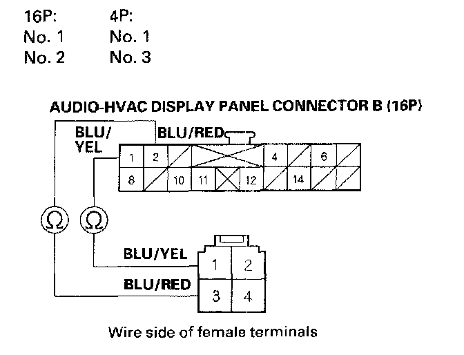
18. Check for continuity between the given terminals of audio-HVAC display panel connector B (16P) and power transistor 4P connector.
Is there continuity?
YES - Go to step 19.
NO - Repair any open in the wire(s) between the audio-HVAC display panel and the power transistor.
19. Reconnect audio-HVAC display panel connector B(16P).
20. Test the power transistor.
Is the power transistor OK?
YES - Check for loose wire or poor connections at audio-HVAC display panel connector B (16P) and at the power transistor 4P connector. If the connections are good, substitute a known-good audio-HVAC display panel, and recheck. If the symptom/indication goes away, replace the original audio-HVAC display panel.
NO - Replace the power transistor.
21. Disconnect the jumper wire.
22. Disconnect the blower motor 2P connector.
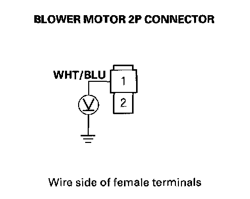
23. Measure the voltage between the No.1 terminal of the blower motor 2P connector and body ground.
Is there battery voltage?
YES - Replace the blower motor
NO - Go to step 25.
24. Turn the ignition switch OFF
25. Remove the blower motor relay from the under-hood fuse/relay box, and test it.
Is there relay OK?
YES - Go to step 27
NO - Replace the blower motor relay.
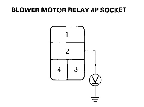
26. Measure the voltage between the No.2 terminal of the blower motor relay 4P socket and body ground.
Is there battery voltage?
YES - Go to step 28.
NO - Replace the under-hood fuse/relay box.
27. Turn the ignition switch ON (II).
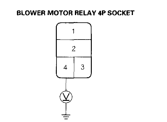
28. Measure the voltage between the No.4 terminal of the blower motor relay 4P socket and body ground.
Is there battery voltage?
YES - Go to step 30.
NO - Repair open in the wire between the No.30 fuse in the driver's under-dash fuse/relay box and the blower motor relay.
29. Turn the ignition switch OFF.
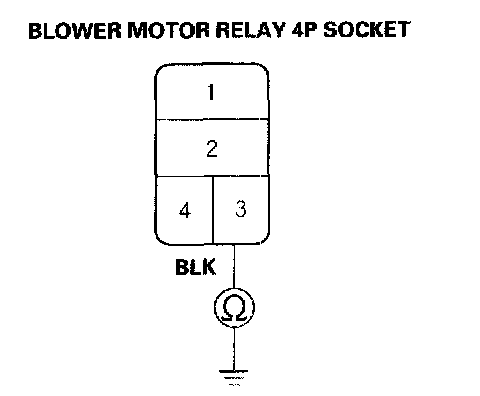
30. Check for continuity between the No.3 terminal of the blower motor relay 4P socket and body ground.
Is there continuity?
YES - Repair open in the WHT/BLU wire between the blower motor relay and the blower motor.
NO - Check for an open in the wire between the blower motor relay and body ground. If the wire is OK, check for poor ground at G302.